
The first article introduced the GD6 open-source LoRaWAN gateway as a product. This one opens up the hardware — the reasoning behind each key component choice, and the engineering trade-offs involved.
The GD6’s hardware is not exotic: an ESP32-S3 as the main controller, a Semtech SX1301 or SX1302 as the LoRa concentrator, plus Ethernet, Wi-Fi, and optional 4G backhaul. But making all of these work reliably together inside an indoor gateway enclosure — while keeping the system open-source and customizable — involves a number of deliberate engineering decisions worth discussing.
Main Controller: Why the ESP32-S3 N8R8
The GD6 uses the ESP32-S3-WROOM-1, specifically the N8R8 variant: 8 MB QIO Flash + 8 MB Octal PSRAM, both running at 80 MHz.
This choice is not arbitrary. The GD6 is more than a LoRa data forwarder — it simultaneously runs a web console, handles TLS-encrypted communications, maintains two MQTT connections (one for data forwarding, one for remote configuration), manages a SPIFFS file system, and executes A/B partition OTA verification. All of this running concurrently places non-trivial demands on memory.
Why 8 MB PSRAM matters
The ESP32-S3’s on-chip SRAM is only 512 KB — far too little to run a TLS-enabled web server alongside multi-channel LoRa data buffering. The Octal PSRAM provides 8 MB of additional memory at 80 MHz bandwidth, sufficient to handle data buffering under high channel load and concurrent web console requests. Without adequate PSRAM, high-load operation could result in packet loss or sluggish web response.
8 MB Flash allocation
The 8 MB Flash must accommodate: the application firmware (two copies, one per A/B partition), the SPIFFS configuration file system, and web static resource files. The A/B dual-partition design means two complete firmware images must fit in Flash simultaneously — a key reason why the Flash capacity cannot be too small.
Why not ESP32 or STM32
The classic ESP32 has limited PSRAM support and lacks the Octal PSRAM bandwidth of the ESP32-S3, making web console + TLS performance noticeably worse. STM32 series MCUs are powerful but lack integrated Wi-Fi — adding an external Wi-Fi module increases cost and complexity, and the development ecosystem is less friendly to web applications than ESP-IDF. The ESP32-S3 balances performance, memory bandwidth, Wi-Fi integration, and open-source ecosystem.
The above analysis is based on the GD6’s published specifications and the known capabilities of the ESP32-S3. ManThink’s official documentation does not detail the selection rationale — this section is an engineering analysis based on the specifications.
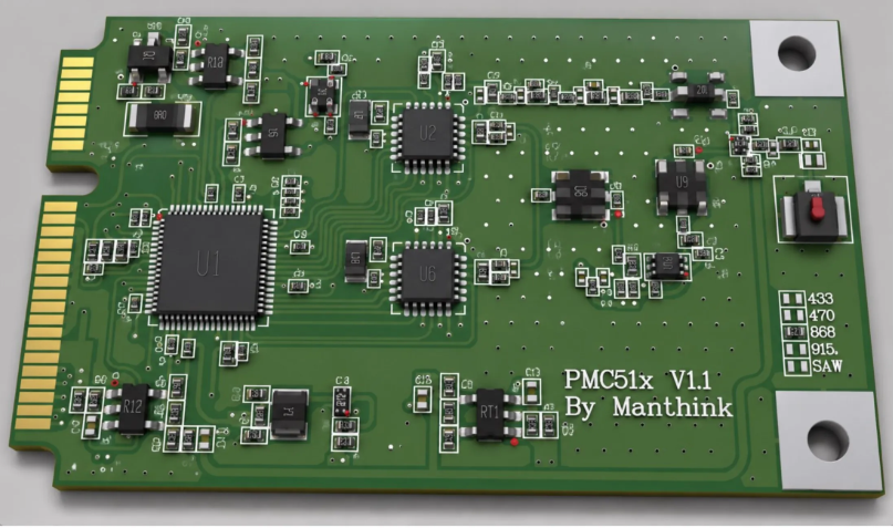
Concentrator: SX1301 and SX1302 in Parallel
The GD6 offers both the SX1301 (model suffix 1) and SX1302 (model suffix 2) concentrator options, rather than choosing only one.
Differences between the two generations
The SX1301 is Semtech’s first-generation LoRaWAN baseband chip, released in 2015. It is well-proven, with extensive community documentation. The SX1302 is the successor, offering improvements in power consumption and sensitivity, with a smaller die area.
Both use the same Type-A LoRa architecture in the GD6: single LoRa antenna, 8 frequency points, 65 channels, half-duplex. This means the RF channel capability is identical regardless of chip choice — the difference lies in the chip’s inherent performance characteristics.
Why both options are retained
Different projects have different requirements. Some customers prioritize cost and proven reliability, where the SX1301 is the sensible choice. Others need lower power consumption or better sensitivity, where the SX1302 is more appropriate. Distinguishing by model suffix makes selection straightforward — no additional configuration discussion needed.
What the Type-A architecture means — and its limits
Type-A is a LoRa structural configuration for Semtech concentrators: one LoRa antenna, 8 frequency points, 65 channels, half-duplex operation. Half-duplex means the gateway cannot transmit and receive simultaneously — it cannot send downlink data during an uplink reception slot, and vice versa.
This is sufficient for most indoor scenarios. Building-internal sensors (temperature/humidity, personnel tracking, energy meters) typically have low uplink frequency and minimal downlink commands, so the half-duplex turnaround delay is not a bottleneck. However, in scenarios requiring dense downlink scheduling (e.g., multicast to large fleets of Class B/C devices), half-duplex limits downlink capacity — a full-duplex solution may be needed in such cases.
The Type-A architecture definition comes from the official GD61x specification. Performance differences between SX1301/SX1302 are based on Semtech’s public materials and general industry knowledge. The GD6 manual does not declare uniform transmit power and sensitivity values — these depend on the specific RF version, front-end, and antenna configuration.
RF Versions: Why GD614 and GD618
The GD6 comes in two RF versions: GD614 (400 MHz class, supporting CN470 and EU433) and GD618 (800 MHz class and above, supporting EU868, AS923, AU915, US902).
Why bands cannot be switched via software
This is a frequently asked question. LoRa RF frequency is determined by hardware: the RF front-end (PA, LNA, filters) and antenna are designed for specific frequency bands. A 400 MHz antenna is extremely inefficient at 868 MHz, and vice versa. Front-end filter passbands are frequency-specific.
Therefore, GD614 firmware will not present an EU868 option, and GD618 will not present CN470. This is not a software limitation — it is a physical one.
Why two versions instead of one wideband version
In theory, a wideband RF front-end could cover 400–960 MHz. But this means compromising performance in every band — wider filter passbands introduce more out-of-band interference, and PA efficiency is inconsistent across a wide frequency range. Splitting into two versions allows each version’s RF front-end and antenna to be optimized for its target bands, yielding better performance and regulatory compliance.
Global coverage strategy
The two versions together cover the world’s major LoRaWAN bands:
| Version | Frequency Range | Supported Regions |
| GD614 | 400 MHz class | CN470 (China), EU433 (Europe 433) |
| GD618 | 800 MHz class and above | EU868 (Europe 868), AS923-1~4 (Asia-Pacific), AU915 (Australia), US902 (North America) |
The region code must match the RF hardware and local regulations. The US902 code in the model name corresponds to the LoRaWAN US915 (902–928 MHz) regional parameter.
Backhaul: Triple-Link Design with Automatic Failover
The GD6’s backhaul design is one of the features that distinguishes it from many gateways in its price range. Not all gateways offer Ethernet, Wi-Fi, and 4G simultaneously.
Ethernet: W5500
The GD6 uses the W5500 Ethernet controller — 10/100 Mbps, RJ45 interface. The W5500 is a hardwired TCP/IP stack chip: Ethernet protocol processing happens inside the chip, not on the main controller’s CPU. This matters for the ESP32-S3 — the main controller needs its cycles for LoRa data processing and web serving, not for running a software network stack.
Ethernet supports DHCP or static IP, with configurable gateway and primary/secondary DNS. The web console includes an “Ethernet Power” option that controls the runtime power of the gateway’s internal Ethernet controller — it is not external PoE output.
Wi-Fi: Concurrent AP + STA
The ESP32-S3’s built-in 2.4 GHz Wi-Fi supports concurrent AP (hotspot) and STA (client) operation. This means the gateway can connect to on-site Wi-Fi as a backhaul link (STA) while simultaneously providing the LGW-Config hotspot for local management (AP).
Design considerations for AP + STA concurrency:
- STA mode serves as a backhaul link, connecting to on-site Wi-Fi — suitable for deployments without wired networking.
-
AP mode operates independently of the backhaul link, always providing a local configuration entry point. Even if all backhaul links fail, an administrator can still connect to the hotspot and access the web console at
192.168.4.1for troubleshooting. - Default hotspot SSID:
LGW-Config, password:lgw12345678, management address:192.168.4.1.
4G: LTE Cat 1 + miniPCIe
4G is an optional configuration (model G includes 4G and PoE; N does not). The 4G module uses a miniPCIe interface and can be swapped to match different carrier frequency bands.
The default 4G module is LTE Cat 1, supporting the following bands:
| Type | Bands |
| LTE-FDD | B1 / B3 / B5 / B8 |
| LTE-TDD | B34 / B38 / B39 / B40 / B41 |
LTE Cat 1 positioning: uplink/downlink rates are more than sufficient for LoRaWAN gateway backhaul (typically tens of KB per second), while power consumption and cost are far lower than Cat 4/6 modules. For industrial sites or temporary deployments without wired networking, Cat 1 is a cost-effective choice.
The miniPCIe interface allows module replacement — if a project is deployed overseas, a 4G module supporting local bands can be installed without replacing the entire gateway. The SIM card uses an external slot. If the SIM has a PIN set, it must be entered (4–8 digits) in the web console.
Link Priority and Automatic Failover
Default link priority: Ethernet > Wi-Fi STA > 4G.
- Ethernet and Wi-Fi STA provide automatic primary/backup failover: Ethernet is used when healthy; on failure, traffic switches to Wi-Fi STA.
- Models with 4G add it as a third link: when both Ethernet and Wi-Fi STA are unavailable, traffic switches to 4G.
The significance of this design: in most indoor scenarios, Ethernet is the primary link, Wi-Fi is backup, and 4G is the last resort. The probability of all three links failing simultaneously is extremely low, dramatically improving backhaul reliability.
Power Supply: Three Options and One Constraint
The GD6 supports three power supply methods:
| Method | Voltage | Use Case |
| Type-C | 5V DC | Desktop debugging, development |
| DC terminal | 5–24V DC | Industrial wide-voltage supply |
| PoE | via RJ45 | AG config only — power and data over one cable |
Why PoE is bundled with 4G
PoE is only available in the G configuration (which includes both 4G and PoE). This bundling logic is sound: PoE primarily serves deployments that need simplified cabling (e.g., ceiling mounts where running a power cable is impractical), and these scenarios often also require 4G backhaul (locations without wired networking typically lack power outlets too). Packaging the two covers the “no network, no power” remote indoor deployment case.
The N configuration (without 4G) targets standard indoor scenarios with Ethernet and power available — PoE is not needed.
Why simultaneous power sources are not recommended
The manual explicitly states that connecting multiple power sources simultaneously is not recommended. Without ideal ORing circuitry between power paths, simultaneous connection can cause current backfeed or voltage conflicts. The GD6 is designed for the user to select one power method, not for power redundancy. If a project requires power redundancy, it should be solved with an external UPS — not by plugging in both Type-C and DC simultaneously.
The A+ / B- terminals
The DC terminal block has four positions: 5–24V, G, A+, B-. The A+ and B- are reserved RS-485 interfaces with no user functionality in the current version. The manual warns against connecting power to these terminals.
A/B Dual-Partition OTA: From Design to Recovery
The GD6’s firmware upgrade uses an A/B dual-partition design — a more robust approach than single-partition with backup.
How it works
- The gateway Flash contains two firmware partitions (A and B). One is active; the other is inactive.
- During upgrade, new firmware is written to the inactive partition.
- After writing completes, the firmware is verified.
- If verification passes, the boot partition switches to the newly written one.
- The next boot loads from the new partition.
Interruption recovery
If power loss, network disconnection, or verification failure occurs during upgrade:
- New firmware not fully written or verification failed → boot partition does not switch → device boots normally from the original active partition.
- New firmware written but boot fails → the manual recommends waiting for automatic restart. If still inaccessible, use Wi-Fi AP or controlled serial recovery — do not repeatedly power-cycle.
Why A/B instead of single-partition + backup
In a single-partition + backup scheme, the backup partition typically stores only a minimal recovery image with limited functionality. In the A/B scheme, both partitions contain complete firmware — a fully usable system is always available. If issues are found after upgrade, you can switch back to the previous version without reflashing.
The trade-off is Flash space — two complete firmware partitions consume twice the space of a single partition, which is one reason the GD6 requires 8 MB of Flash.
Firmware source
Firmware .bin files can be self-built — the GD6’s firmware and web configuration system are open-source on GitHub (github.com/ManThink/gd6-open). Upload and flash via the “Firmware Upgrade” page in the web console.
The manual warns: do not upload a full Flash manufacturing image as a Web OTA firmware. Use a .bin firmware that matches the gateway model, hardware version, and target region.
Storage and Configuration: SPIFFS and web/ Directory Protection
SPIFFS file system
The GD6 uses SPIFFS (SPI Flash File System) for configuration storage. Configuration JSON files under /spiffs store all settings — network, LoRaWAN, MQTT, etc. Configurations take effect after restart and survive power loss.
The web console’s “File System” page provides direct management of /spiffs files, supporting viewing and editing configuration JSON. This opens a path for deep customization — advanced users can modify configuration files directly, beyond the options exposed in the web interface.
web/ directory protection
The /spiffs/web/ directory stores the web console’s static resources (HTML, CSS, JS). The manual contains an explicit warning:
- Overwriting
web/files may render the console inaccessible. - Factory reset does not restore damaged web files.
- Do not modify this directory unless performing controlled maintenance.
This design is somewhat paradoxical — the file system is open, but the web resource files are off-limits. In practice, this is a reasonable layering: configuration files are open for user customization, while web resources are system components whose modification carries high risk and falls outside normal usage. If web interface customization is genuinely needed, the correct approach is to build from source — not to overwrite files online.
Power-loss-safe configuration
Once SPIFFS writes to Flash, the data is persistent and does not depend on RAM. This means configurations survive immediate power loss after writing. However, configuration changes require a restart to take effect — after modifying a configuration JSON, the gateway must be restarted for the new settings to apply.
Factory reset boundaries
Holding the REC button for 2 seconds triggers factory reset. The scope:
-
Reset: network, LoRaWAN, MQTT, remote configuration, 4G settings, login password (reverts to
wifi!0804). - Preserved: the written Gateway EUI.
-
Not restored: web static files (
web/directory).
The Gateway EUI is the gateway’s unique identifier, typically written at factory or first configuration. Preserving it through factory reset means the gateway’s registration on the network server is not invalidated by the reset.
Other Hardware Design Details
Antenna design
Only the LoRa antenna is external on the GD6 (SMA connector). Wi-Fi and 4G antennas are internal. This design reduces external cabling and simplifies installation — the user only needs to connect one antenna.
The manual emphasizes: connect the LoRa antenna before powering on. Transmitting from the LoRa concentrator without an antenna connected will damage the front-end PA.
LED indicator
| State | Pattern | Meaning |
| Normal operation | Slow blink (1s on / 1s off) | System running normally |
| Factory reset | Solid at 2s → 3 fast blinks → restart | Performing factory reset |
The LED patterns are minimal — primarily indicating run state and factory reset progress. For detailed link status (Ethernet/Wi-Fi/4G connection state, LoRa service state), the web console’s overview page must be consulted.
RS-485 reserved interface
The A+ and B- terminals on the DC block are reserved RS-485 interfaces with no user functionality in the current version. These may be expansion interfaces reserved for future or custom versions.
Physical installation
Desktop placement or wall mount using the bottom rotating bracket. The manual warns against blocking the bottom ventilation holes — the ESP32-S3 + SX1302 + 4G module generates some heat under full load, and bottom ventilation is part of the passive cooling design.
Hardware Specifications Summary
| Category | Specification |
| Main controller | ESP32-S3-WROOM-1 N8R8 |
| Flash | 8 MB QIO, 80 MHz |
| PSRAM | 8 MB Octal, 80 MHz |
| LoRa concentrator | Semtech SX1301 (suffix 1) or SX1302 (suffix 2) |
| LoRa architecture | Type-A: single antenna, 8 freq points, 65 channels, half-duplex |
| Channel bandwidth | Multi-channel default 125 kHz; LoRa Std configurable |
| RF version | GD614 (400 MHz class) / GD618 (800 MHz class and above) |
| Region support | CN470, EU433, EU868, AS923 (1~4), AU915, US902 |
| Ethernet | W5500, 10/100 Mbps, RJ45 |
| Wi-Fi | 2.4 GHz, AP + STA concurrent |
| 4G (optional) | LTE Cat 1, miniPCIe, replaceable module |
| 4G bands (default module) | FDD: B1/B3/B5/B8; TDD: B34/B38/B39/B40/B41 |
| Link failover | Ethernet > Wi-Fi STA > 4G, automatic |
| Power supply | Type-C 5V / DC 5–24V / PoE (AG config only) |
| OTA | A/B dual-partition |
| Config storage | SPIFFS, power-loss safe |
| Management | Web console (CN/EN), REST API, remote MQTT |
| Security | TLS certificates, Token auth, password login |
| Antennas | LoRa external; Wi-Fi / 4G internal |
| Installation | Desktop or wall mount with rotating bracket |
Summary
The GD6’s hardware design philosophy can be summarized as: use proven chip solutions for reliable engineering implementation, and leave flexibility to the software and open-source layer.
Choosing the ESP32-S3 N8R8 is not about pushing performance limits — it is about finding the balance point between memory, Wi-Fi integration, development ecosystem, and cost. Offering both SX1301 and SX1302 is not technical indecision — it covers different project needs. The combination of triple-link backhaul + A/B dual-partition OTA + SPIFFS configuration management gives this gateway a reasonable position between “plug-and-play” and “deeply customizable.”
The next article moves from hardware to software — how to use the GD6 open-source repository: cloning the code, building firmware, customizing the web configuration system, and calling the REST API.
Related Links
- GD6 open-source repository (firmware + web config system): github.com/ManThink/gd6-open
- GD61x Specifications & User Guide: think-link.net/docs/zh/Device/LoRaWANGateway/gd61x-user-guide
- GD6 Configuration Guide: think-link.net/docs/zh/Device/LoRaWANGateway/gd6-configuration-guide
- Article 1: ManThink Launches GD6 Open-Source LoRaWAN Gateway: ESP32-S3 + SX1302 Indoor Solution
- ThinkLink Platform: www.think-link.net
- ManThink Website: www.manthink.cn